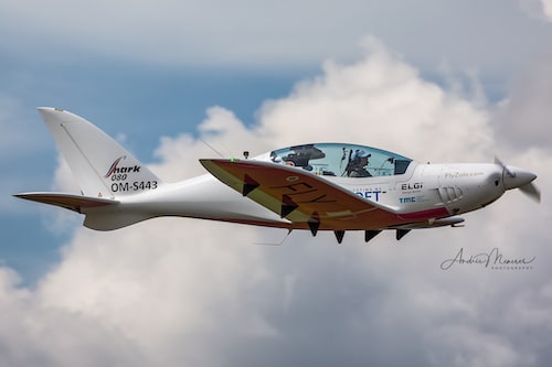
Shark Aero company designs and manufactures ultralight sport aircrafts with two-seat tandem cockpit. For design development they use popular open-source software package openFOAM [1]. The CFD (Computational Fluid Dynamics) simulations use the Finite Elements Method (FEM). After the model is created, using a Computer-Aided Design (CAD) software, it is divided into discrete cells, so called “mesh”. The simulation accuracy depends strongly on mesh density with the computational and memory requirements rising with the 3rd power of the number of mesh vertices. For some simulations the computational demands can be a limiting factor. Workflow transfer into High-Performance Computing (HPC) environment was thus undertaken, with a special focus on the investigation of computational tasks parallelization efficiency for a given model type.
METHODS
Compute nodes with 2×6 cores Intel Xeon L5640 @ 2,27GHz, 48 GB RAM and 2×500 GB were used for this project. All calculations were done in a standard HPC environment using Slurm job scheduling system. This is an acceptable solution for this type of workloads where no real-time response, nor immediate data processing is required. For the CFD simulations we continued to use OpenFOAM & ParaView version 9 software packages. Singularity container was used for calculation deployment, having in mind potential transfer of the workload to another HPC system. The speed-up gained from just straight away transfer to HPC system was approximately 1.5x compared to a standard laptop.
PARALLLEZIATION
Parallelized task execution can increase the speed of the overall calculation by utilizing more computing units concurrently. In order to parallelize the task one needs to divide the original mesh into domains – parts that will be processed concurrently. The domains, however, need to communicate through the processor boundaries i.e. domain sides where the original enclosing mesh was divided. The larger the processor boundary surface is, the more I/O is required in order to resolve the boundary conditions. Processor boundary communication is facilitated by the distributed memory Message Passing Interface (MPI) protocol, and the distinction of difference between CPU cores and different compute nodes is abstracted from user. This leads to certain limitations on efficient usage of many parallel processes, since overly parallelized job executions can be actually slower due to communication and I/O bottlenecks. Therefore, the domains should be created in a way that minimizes the processor boundaries. One possible strategy is to divide the original mesh only in co-planar direction with the smallest side of the original enclosing mesh. By careless division into domains the amount of data to be transferred increases beyond reasonable measure. If one chooses to use mesh division in multiple axes, one also creates more processor boundaries.
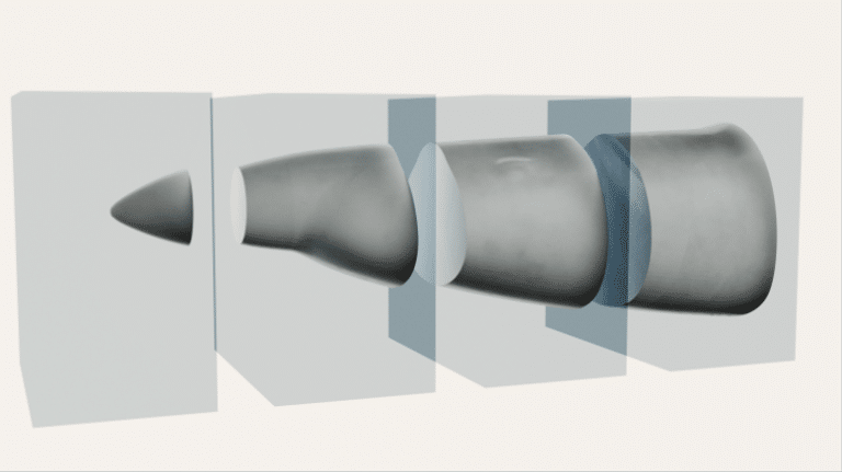
Figure 1: Illustration of mesh segmentation. The encoling mesh is represented by the transparent boxes
The calculations were done in four steps: enclosing mesh creation, mesh segmentation, model inclusion and CFD simulation. The enclosing mesh creation was done using the blockMesh utility, the mesh segmentation step was done using the decomposePar utility, the model inclusion was done using the snappyHexMesh program, and the CFD simulation itself was done using SimpleFoam. The most computationally demanding step is snappyHexMesh. This is understandable from the fact that while in CFD simulation the calculation needs to be done several times for every edge of the mesh and every iteration, in the case of model inclusion one creates new vertices and deletes old ones based on the position of vertices in the model mesh. This requires creation of an “octree” (partitioning of three-dimensional space by recursively subdividing it into eight octants), repeated inverse search, and octree re-balancing. Each of these processes is N*log(N) in the best case scenario, and N2 in the worst case, N being the number of vertices. The CFD itself scales linearly with number of edges, i.e. “close to” linearly with N (only spatially proximate nodes are interconnected).2 We developed a workflow that creates a number of domains that can be directly parallelized with the yz plane (x being the axis of the aircraft nose), which simplifies the decision making. After inclusion of a new model, one can simply specify the number of domains and run the calculation minimizing the human intervention needed to parallelize the calculation.
RESULTS AND CONCLUSION
The relative speedup of the processes calculation is mainly determined by limited I/O. If the computational tasks are well below I/O bounding, the speed is inversely proportional to the number of domains. In less demanding calculations, i.e. for small models, the processes can be easily over-parallelized.
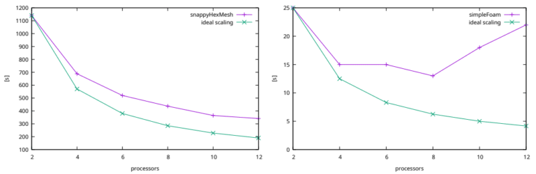
Figure 2: Dependence of real elapsed time on the number of processes for snappyHexMesh and simpleFoam. In the case of simpleFoam the time starts to diverge for more than 8 processes, since the data trafic overcomes the paralellization advantage. Ideal scaling shows the theoretical time needed to finish the calculation, if the data trafic and processor boundary condition resolution was not involved.
Once the mesh density is high enough, the time to calculate the CFD step is also inversely proportional to the number of parallel processes. As shown in the second pair of figures with twofold increase in mesh density, the calculations are below I/O bounding even in the CFD step. Even though the CFD step is in this case comparatively fast to the meshing process, the calculation of long time intervals could make it the most time consuming step.
The aircraft parts design requires simulations of a relatively small models multiple times under altering conditions. The mesh density needed for these simulations falls into medium category. When transferring the calculations to the HPC environment, we had to take into account the real needs of the end user in terms of model size, mesh density and result precision required. There are several advantages of using HPC:
- The end user is relieved of the need to maintain his own computational capacities.
- Even when restricted to single thread jobs the simulations can be offloaded to HPC with high speed up, making even very demanding and precise calculations feasible.
- For even more effective calculations a simple way of utilizing parallelization was determined, for this particular workload. Limitations of parallel runs for the given use case and conditions were identified. The total increase in speed that was reached in practical conditions is 7.3 times. The speed-up generally grows with the calculation complexity and the mesh precision.